Designing a 3D Printed Toy for My Son
This Summer, the theme was bonding with my nearly 6-year-old by unleashing our inner engineers with 3D Printing! As he grows up, his interests are escalating and becoming more concrete. He is now almost 6 and he has a great interest in electronics and mechanics. Since we had a 3D printer, I thought that we could start building something together and start experimenting with things. Such as basic mechanical parts, and some simple and safe electric circuits that he can play with.
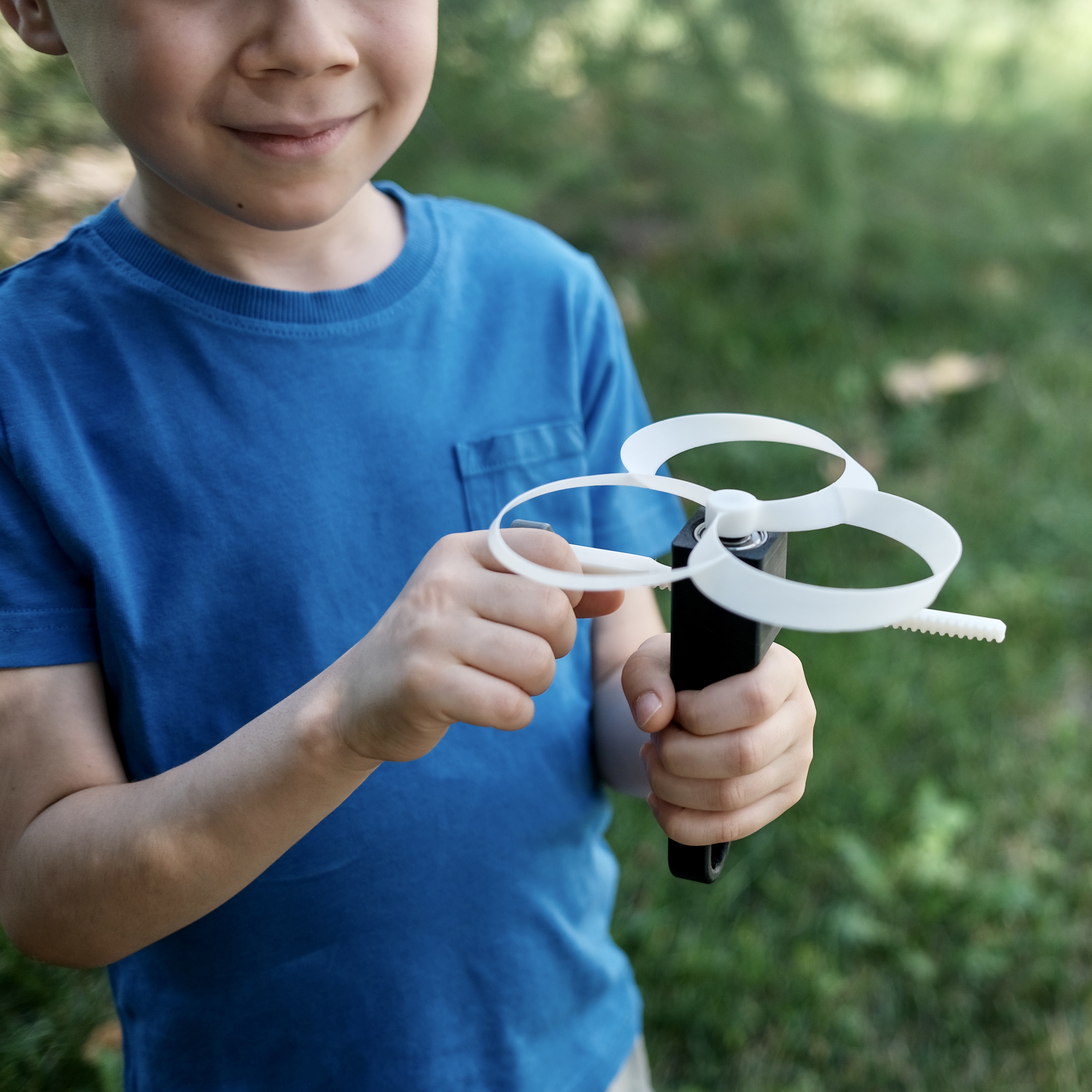
As an unexpected twist in this adventure, I stumbled upon a brilliant idea—what if I could craft a delightful surprise for my son from printables.com? So I downloaded a toy named “Pull copter“, which is a simple device that flies a propeller. The main reason that I’ve picked this specific toy is that it contains a tiny gear that could exemplify force transmission. It became an instant hit, captivating not just my son but also my niece. The sight of their gleeful laughter and amusement filled my heart with parental pride. After all, there’s nothing quite like the joy of knowing your child is having a blast, while you are also having a great time :)
This is the 3D drawing of the toy that I’ve printed:
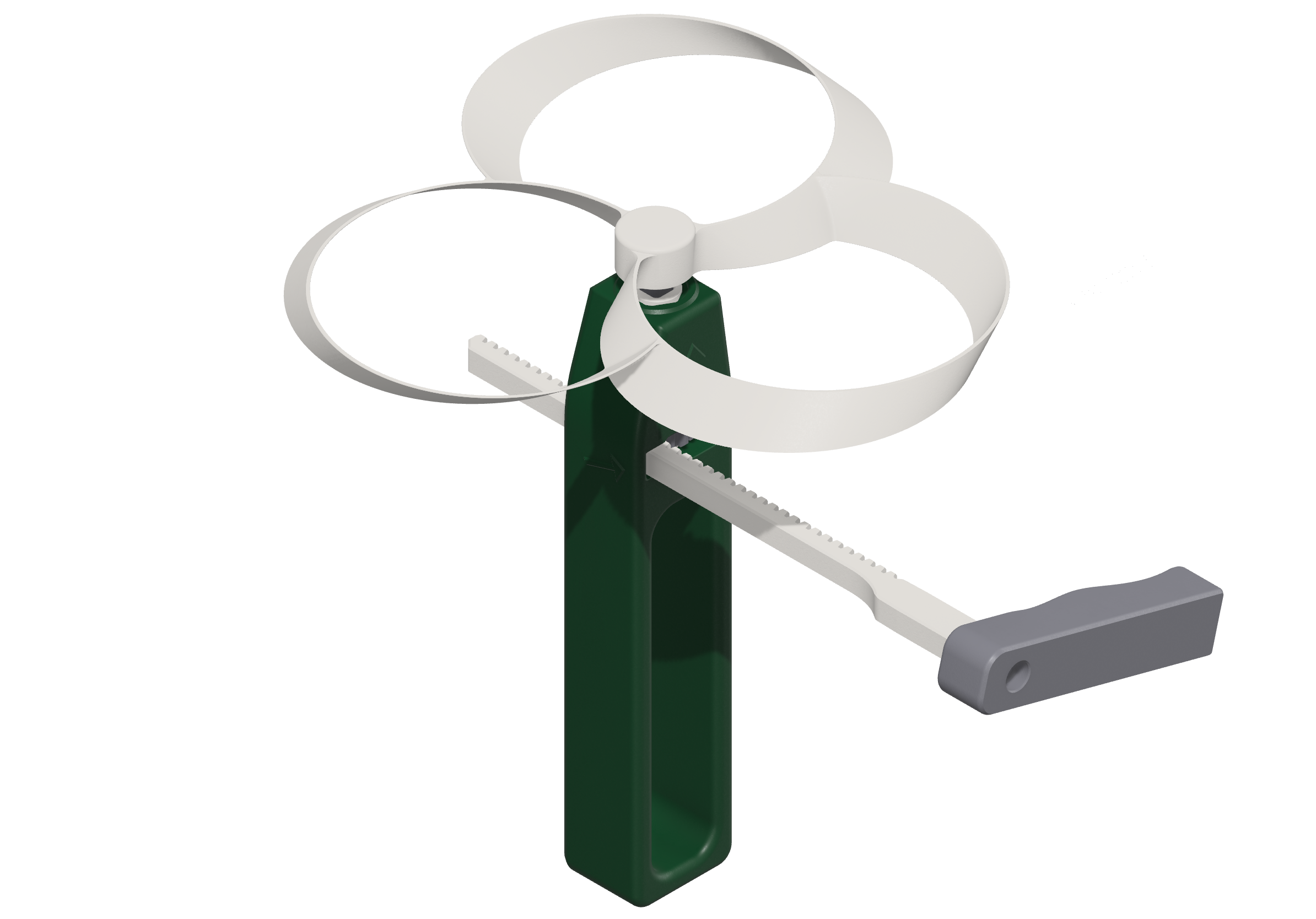
But suddenly my son came to me crying, because he injured his hand by having a little cut on his index finger. The accident happened due to he held the handle wrong and when he pulled the rod, the friction caused the injury. The toy has a giant hole in the handle part so that your fingers would be protected. But it doesn’t apply to everyone, especially for kids being a bit sloppy, they forget to take care of this stuff, especially in the middle of a “fun moment”.
As a parent, you don’t want your kids to get hurt.
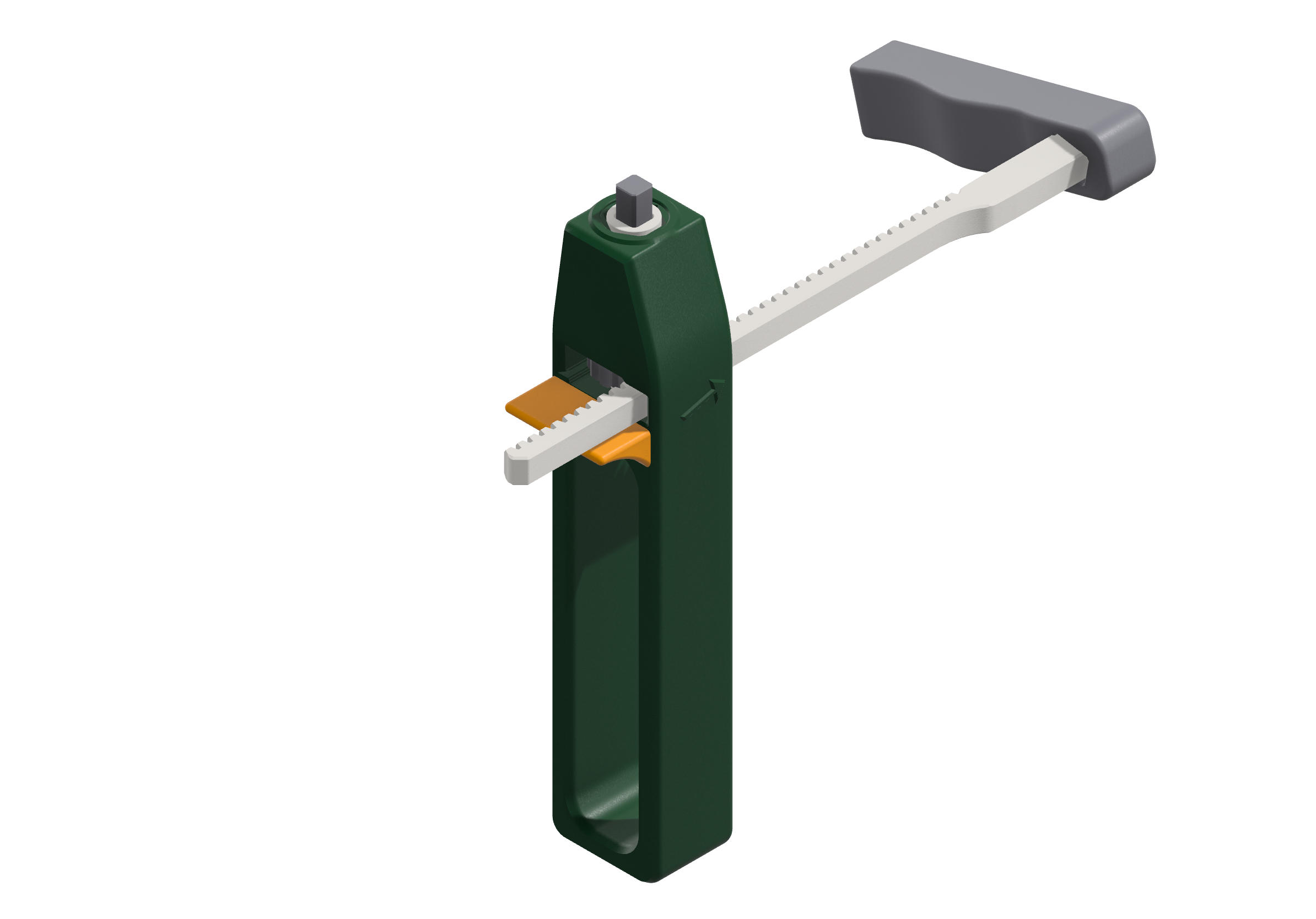
I immediately put the toy into pieces and my initial thought was to simply add a guard below where the pull rod travels, print that part, and call it a day. You can look at the yellow addition below. Basically when assembled it would make it something like this:
But then I reminded myself, that this would be a great opportunity to practice the design principles of a designer I admire; Dieter Rams. The admiration started when I decided to install a Vitsœ 606 Universal Shelving System for my apartment. He is an industrial designer who had a big impact on Apple’s design language today, And he is well known for his designs for the consumer products company Braun, and the furniture company Vitsœ.
So what were the design principles, you might ask? I won’t be going into each one, but you can find brief information about these principles here. My main theme will be making this product more useful, by putting some thought down to the last detail and designing as little as possible.
Before jumping into our interpretation of this toy, let’s examine what the original product consists of.
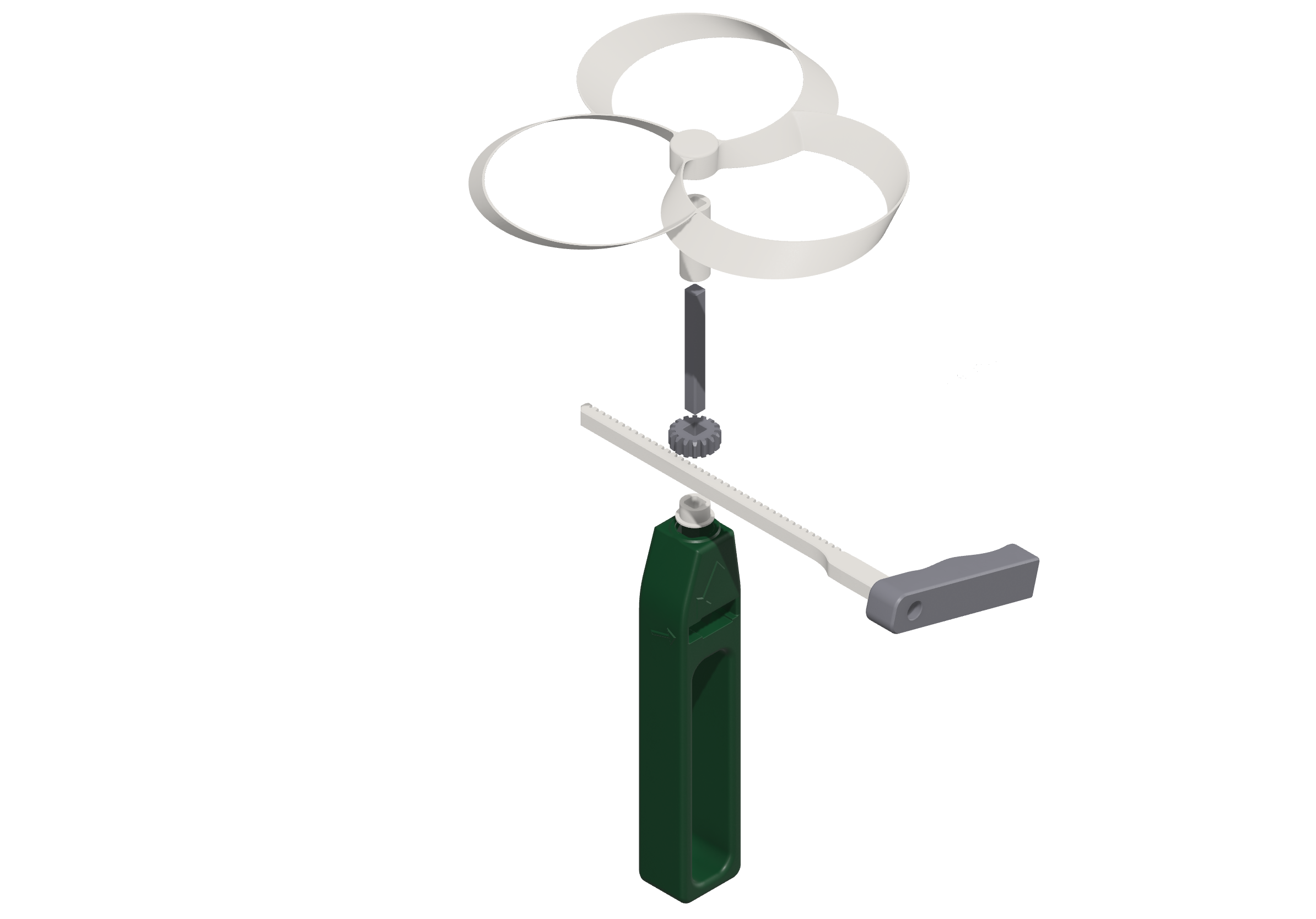
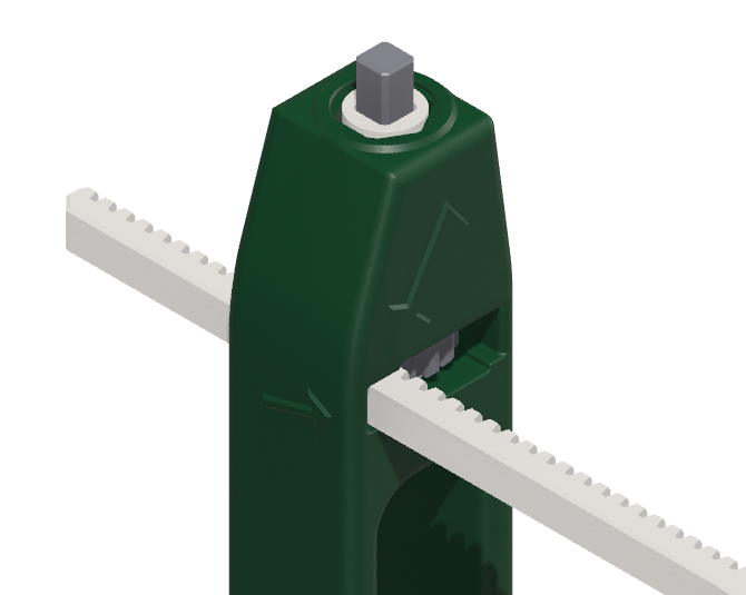
As you can see, the pull rod rotates the main gear and that motion is transferred to the propeller by the main axle. There are two bearings so that the axle can have a reasonable amount of friction while also being stable on the Z axis. If we slowly put down these parts together it will look like this within the handle.
At this point, we can come up with a few requirements that we can follow during the preliminary design. The first one would be the main requirement, design it in a way that a person should not hold it wrong.
The shape of the handle should prevent injuries from the pulling motion of the pulling rod.
As someone who has a good amount of experience in systems design, I have to admit that this is a considerably vague requirement, but we are not that serious here. The next requirement would be, that we can improve how the main axle spins by simply improving its stability.
Reduce the losses that have been caused by the main axle spin
The last one is make design it as little as possible. Removing the arrows in the original design and making it obvious where the pull rod should go. The arrows that I don’t like:
Reduce the design elements and improve ergonomics
Again, ergonomics and quantity of the design elements may be a very subjective topic. On the whole, I think this should go hand in hand with the Good design makes a product understandable principle.
It’s worth mentioning that I am not going to redesign the propeller and the gears as it requires lots of knowledge in various fields, for instance, aerodynamics. I have almost zero knowledge of these subjects and I will keep the propeller as it is and also don’t make big adjustments on the gears.
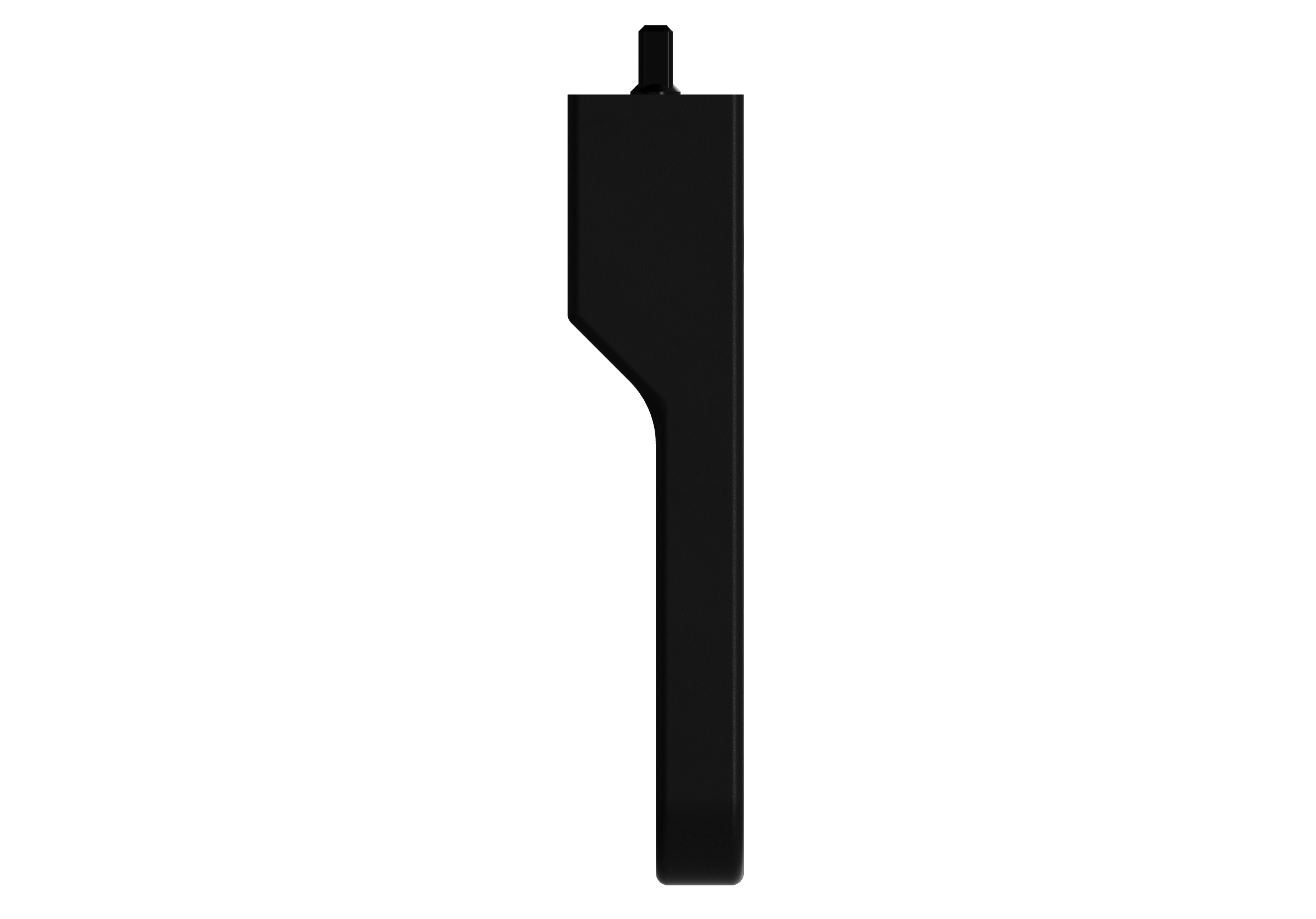
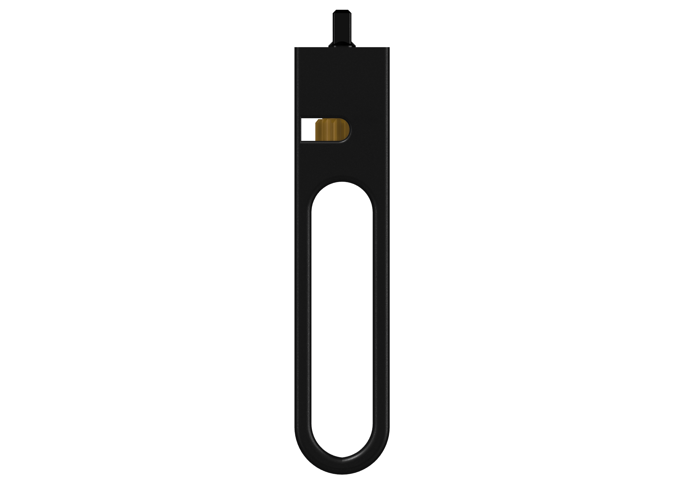
Let’s dive into the design! The main body will be in a form as follows so that we can address the first requirement. The handle will taper down, or on the opposite side, the upper part will be slightly wider. The handle would look like this from the left side:
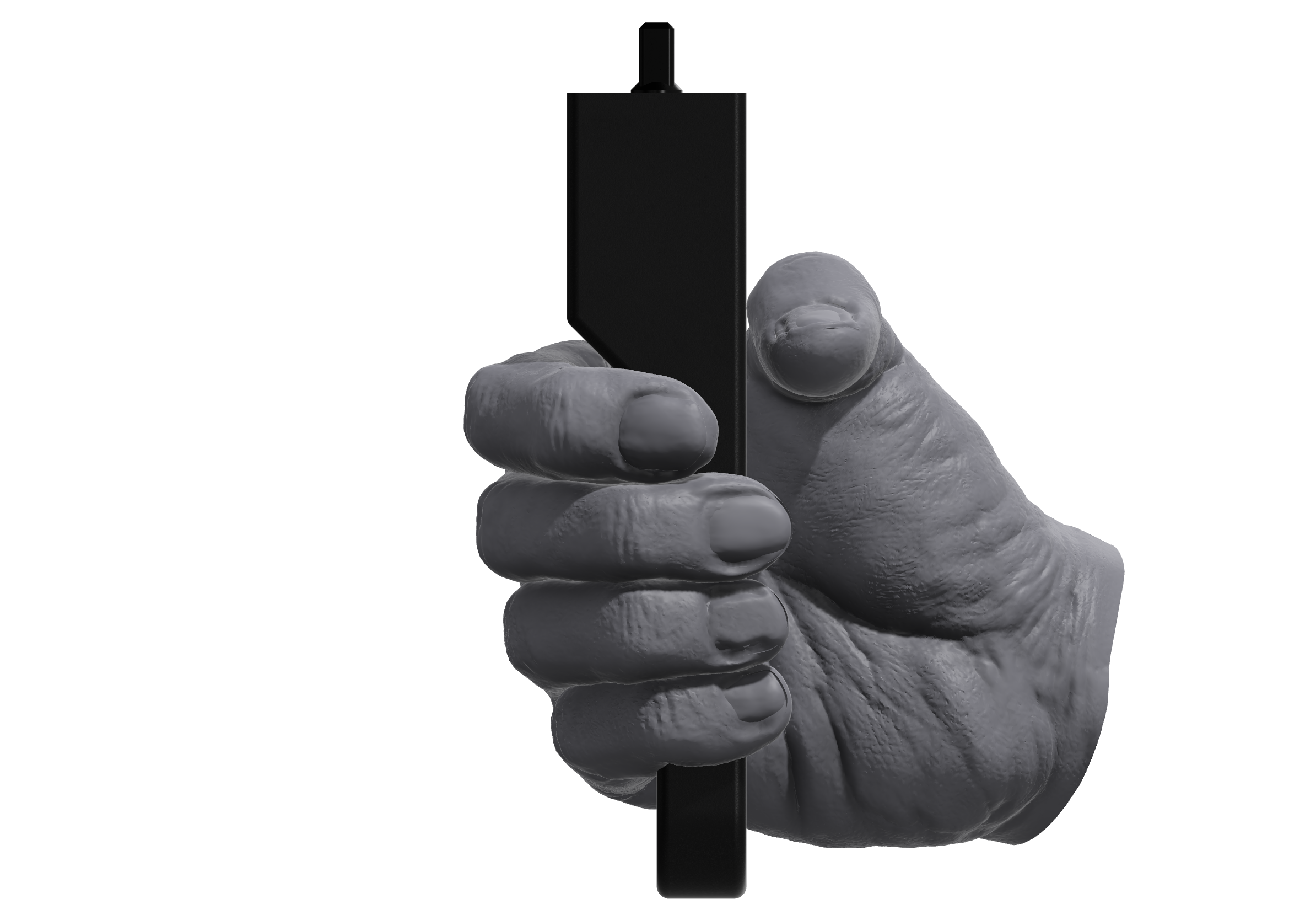
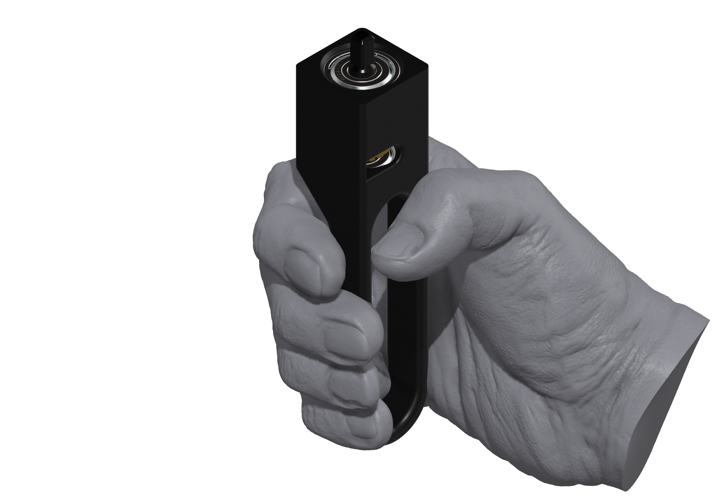
If we put a human hand into the design, it should be handled like below:
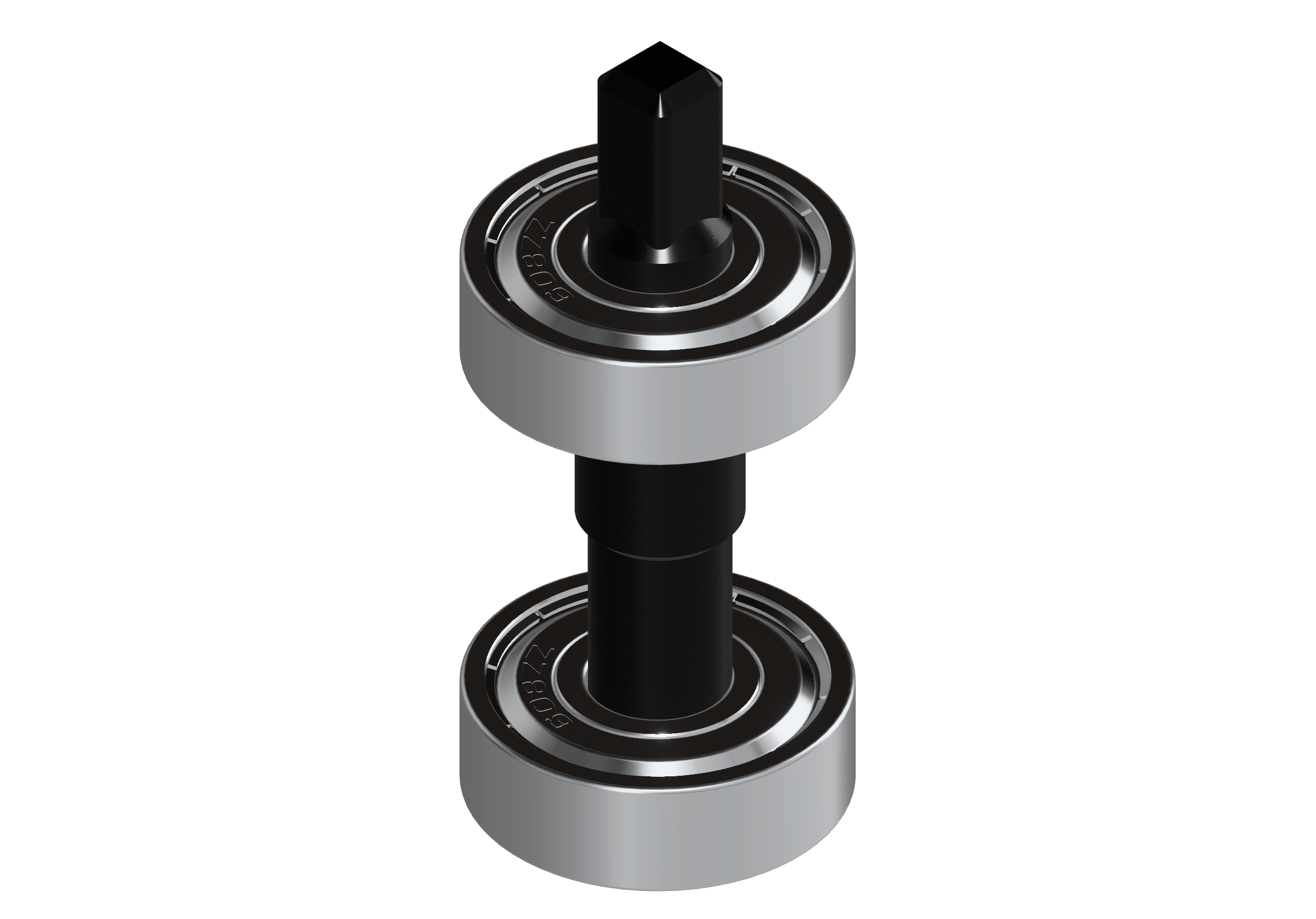
The second requirement was reducing the losses and stabilizing the main axle. For this requirement, I had to rethink the all moving parts. The first thing that came into my mind was using ball bearings to stabilize the rotation. Ball bearings are mechanical components used in rotating applications to reduce friction and enable smooth rotational motion. They consist of small, spherical balls held within a ring-like structure. The balls roll between the inner and outer rings so that it can reduce friction. These parts can be found easily and they are relatively cheap.
Also if I can reduce the losses while spinning the main axle, I can reduce the size of the pulling rod, which is prone to break. Because we can get to the speed where the propeller can generate enough lift. Hence I designed the axle and the ball bearings in the following form:
BTW, if you are curious to peek inside this mechanical marvel? Behold, an inside view of the enigmatic ball bearing:
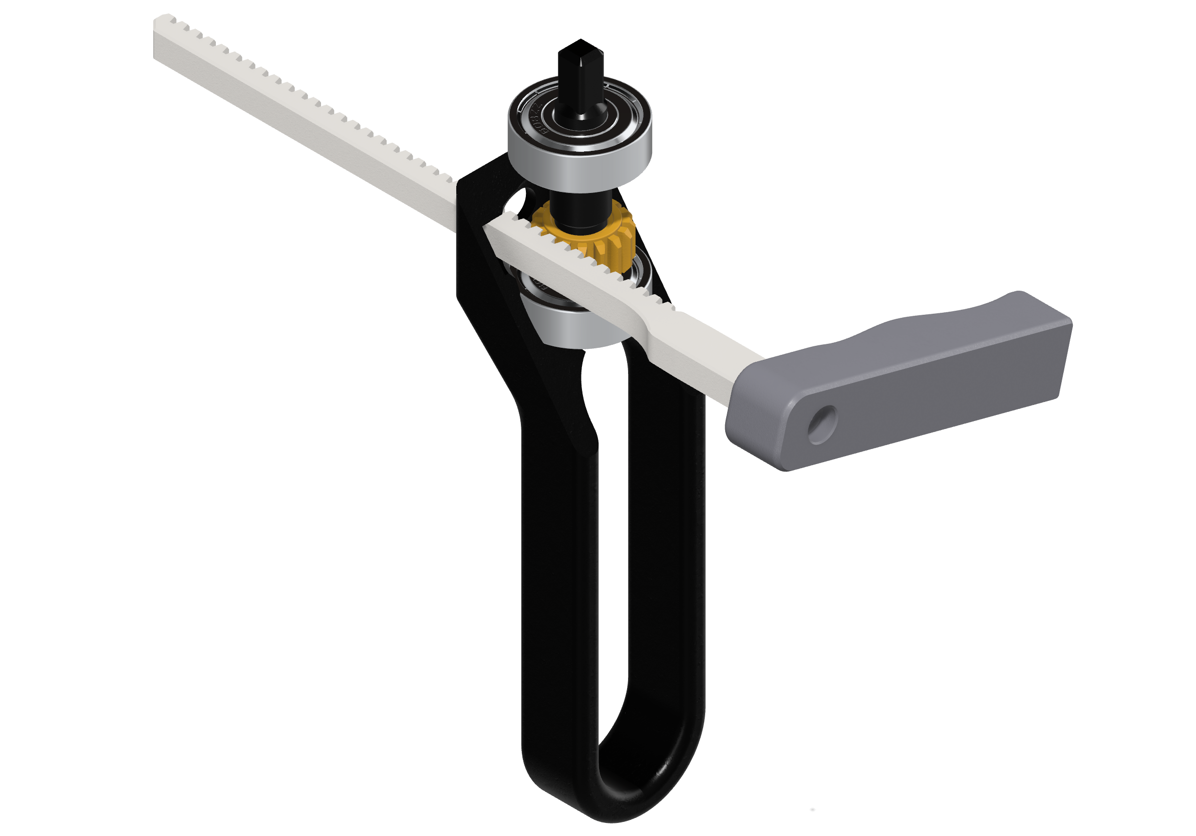
I used 608ZZ ball bearings for my design and the amount of friction and performance may vary by the quality. I think mine are decently enough for my application. And once we place the main gear to the axle, the complete structure will look as follows:
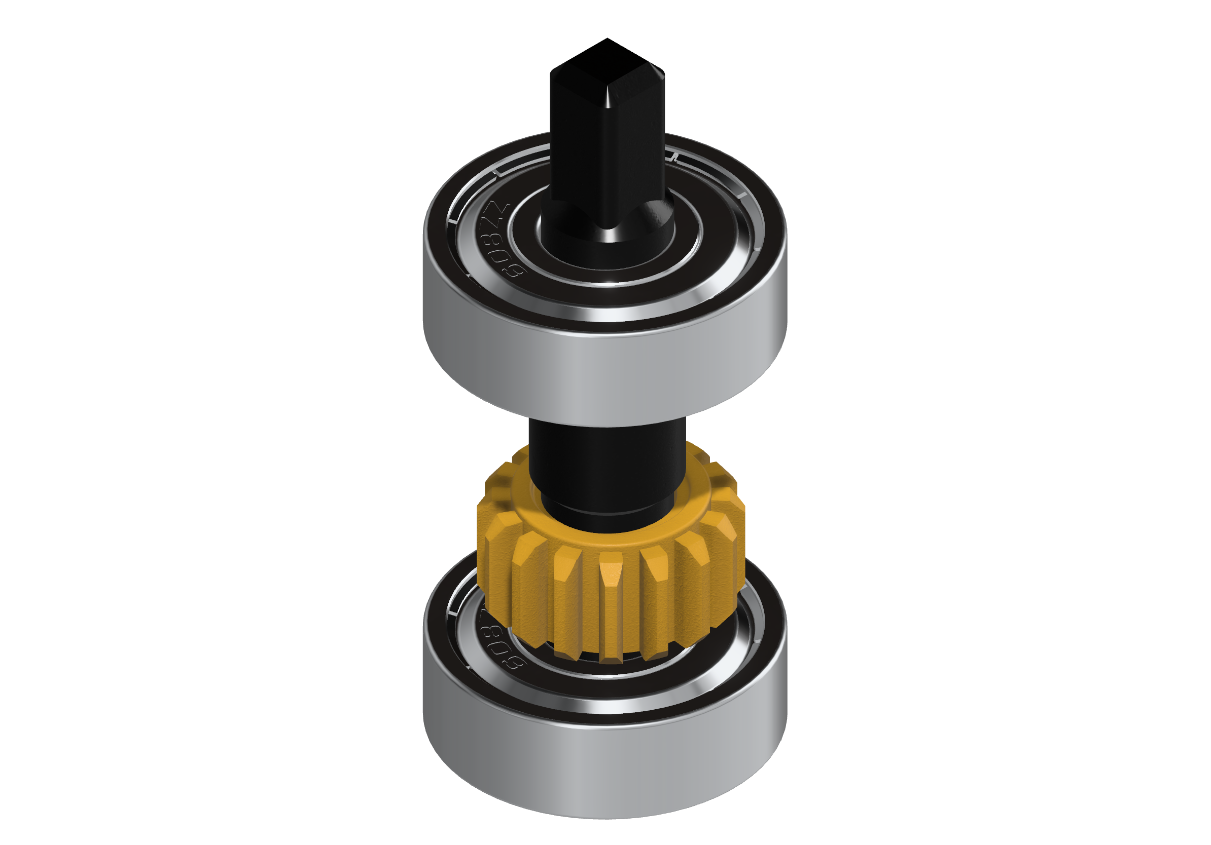
Your eyes might be caught that I picked an eye-catching color for the main gear. It’s related to the third requirement. So let’s address that one as well.
It’s worth mentioning that I also did some experiments and some failures throughout the design process. So I need to make it clear that this process was not that smooth. Here are some examples of my experimental parts that have been printed so far:
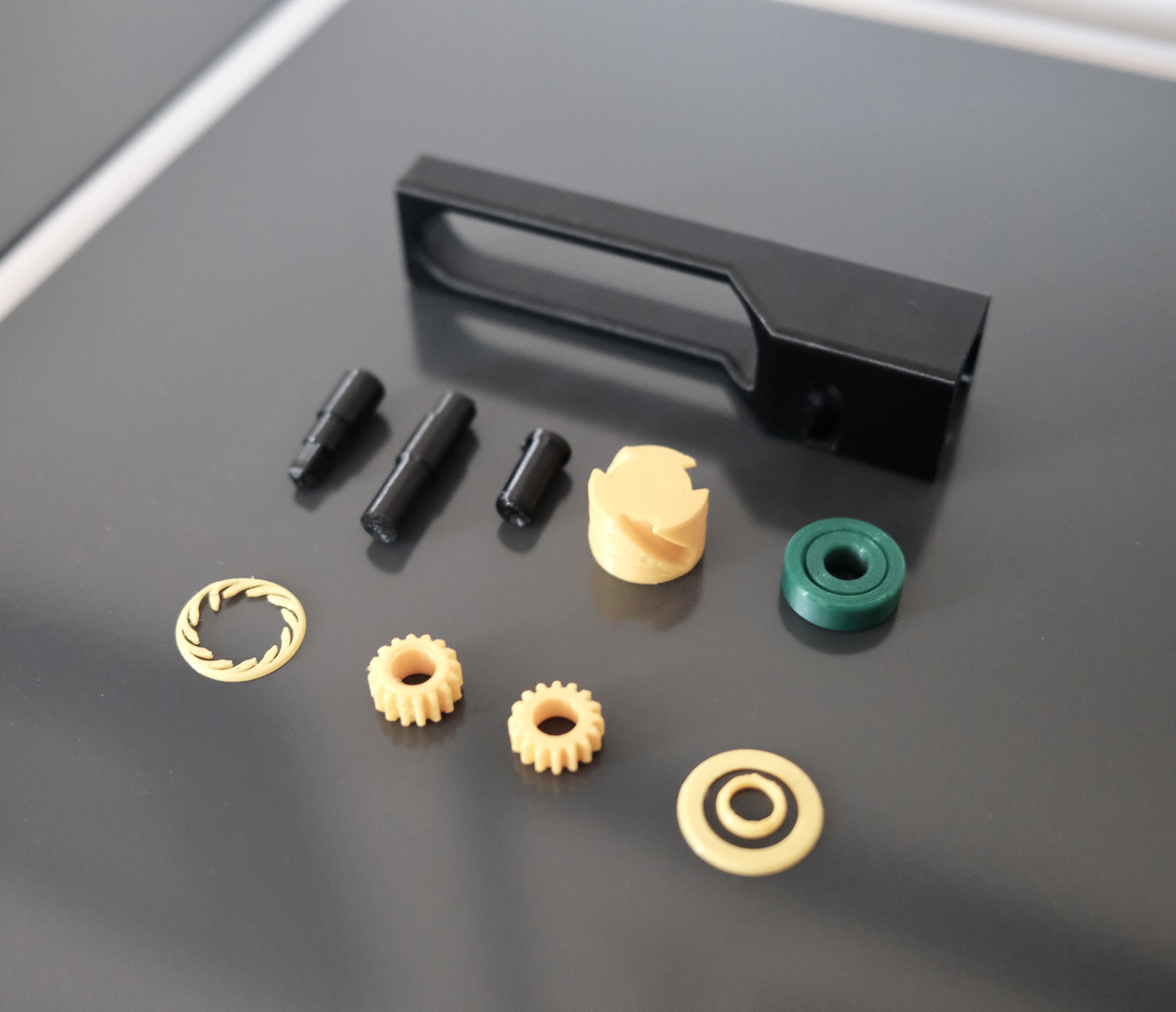
Beyond safety, my second mission with this design was to create something intuitively graspable. Imagine standing in front of it; your gaze instantly locks onto the yellow hue, like a beacon signaling ‘gear.’ With just the right amount of space for inserting the pull rod, I believe it’s a modest execution of form and function.
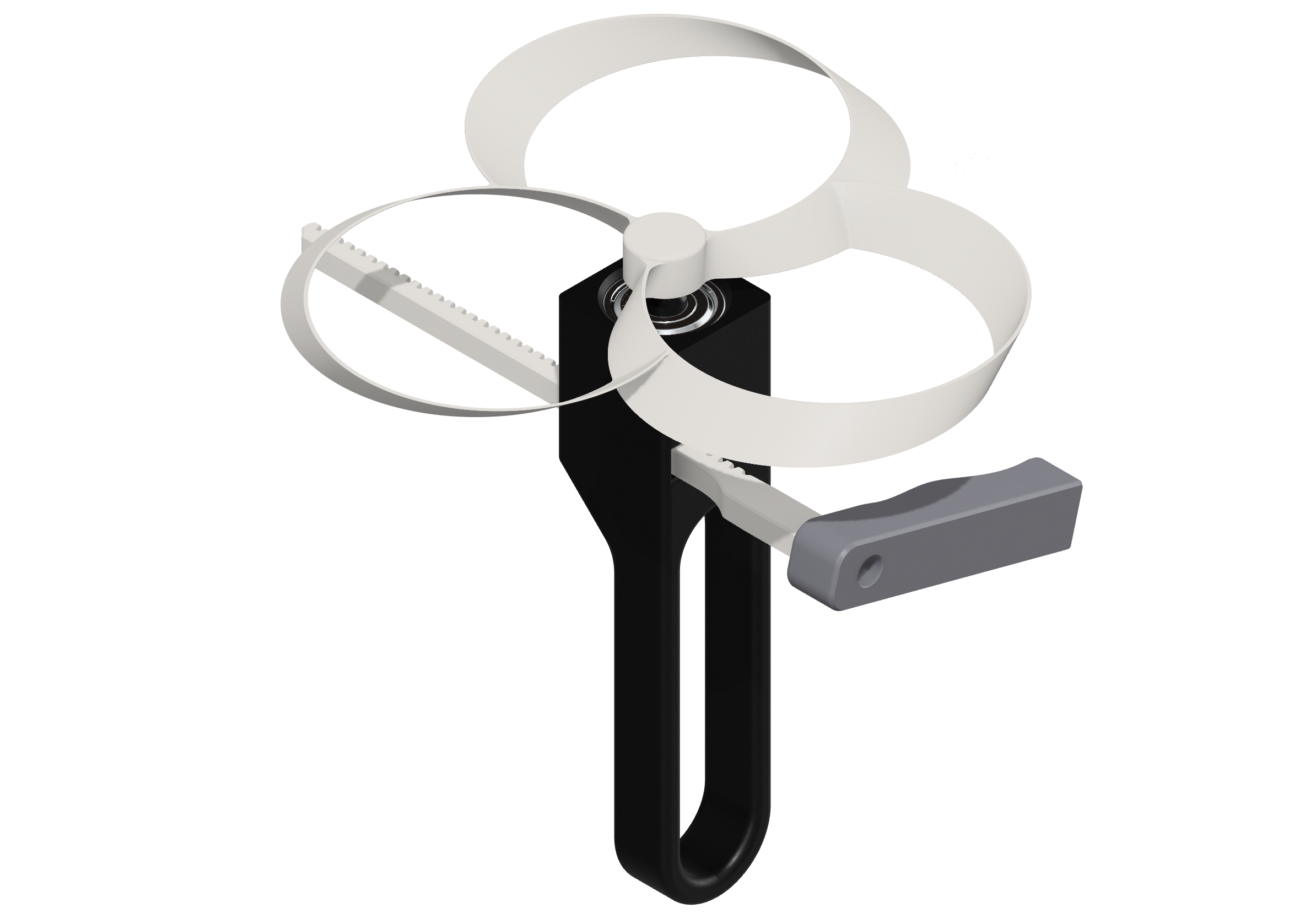
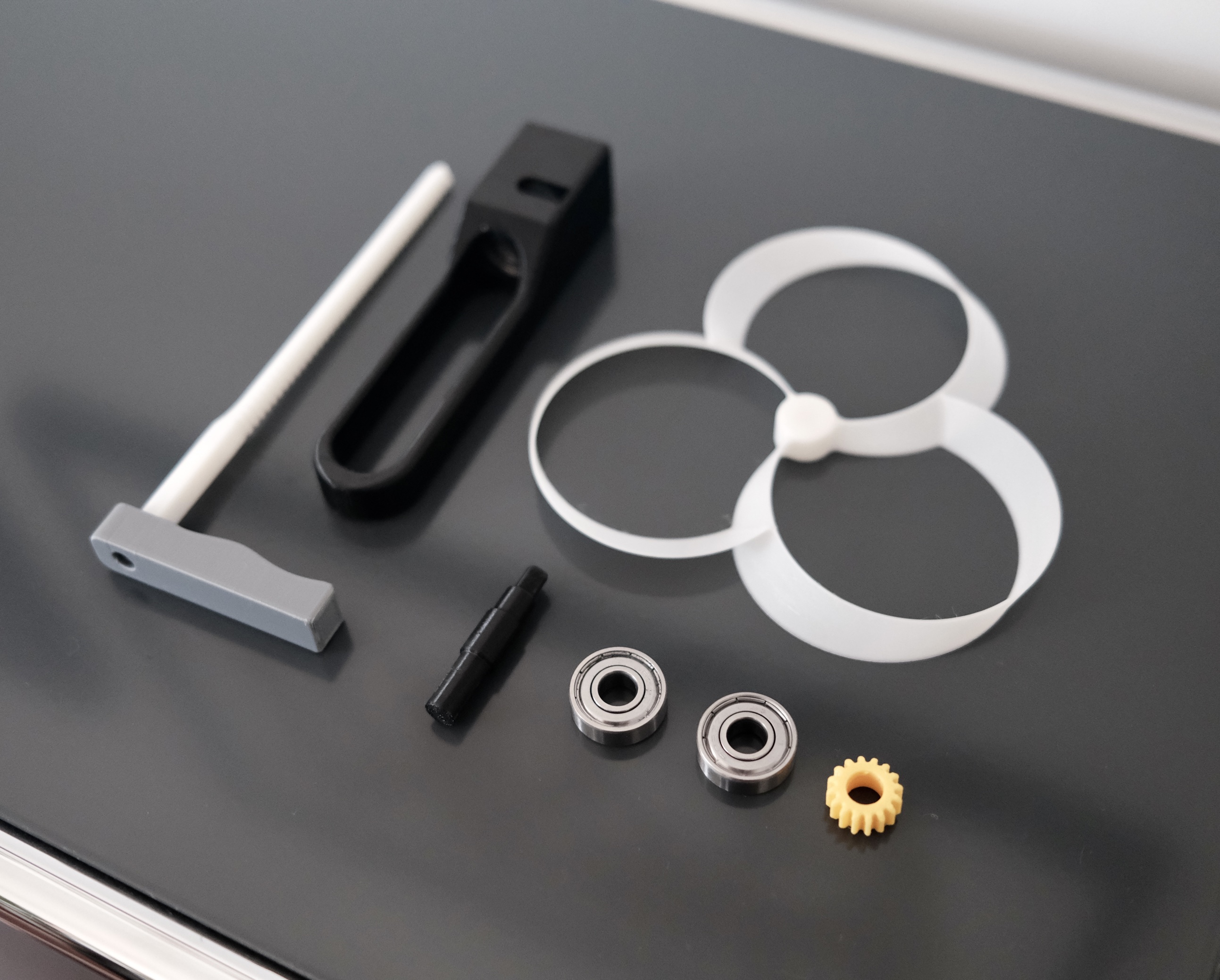
You might noticed that I also made the bottom part round so that it would be more comfy to hold. So, when you lay your eyes on all the components in their scattered arrangement, this is the ensemble that would look like:
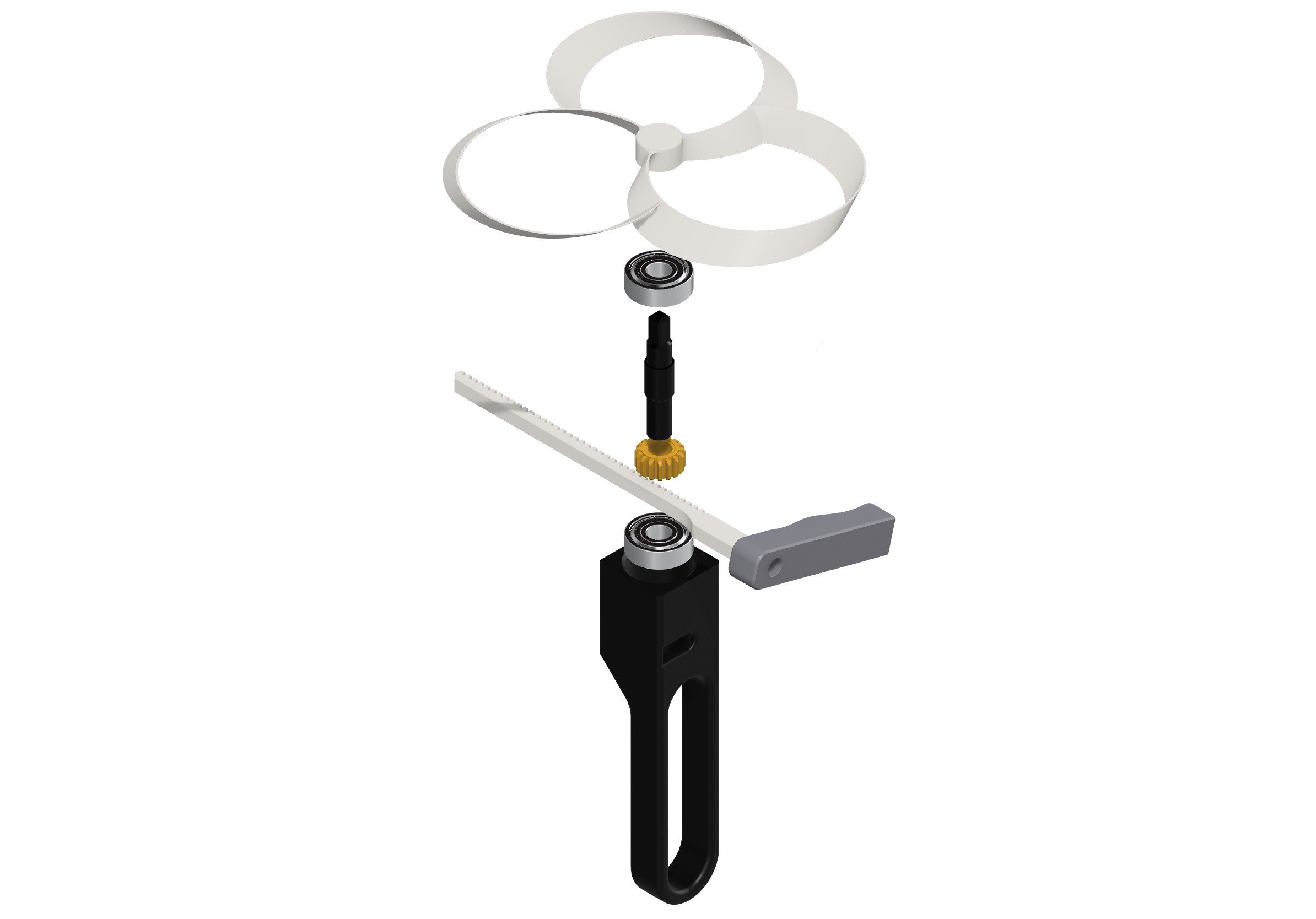
When we put them in place, it should look like this:
When someone grabs it:
And the image of all the assembled components coming together, forming the new design:
As the design reaches its finale, the 3D printer brings the parts to life:
Thrilled with the new design; it’s like creating playtime magic. My kid and I are hooked on it, and I’m gearing up to share the stl file with the world. But, before I hit that ‘upload’ button, let’s gather some insights and fine-tune if needed. As a software engineer not dipping into the world of tangible creations, it’s been an enchanting journey. I’m looking forward to practicing more!
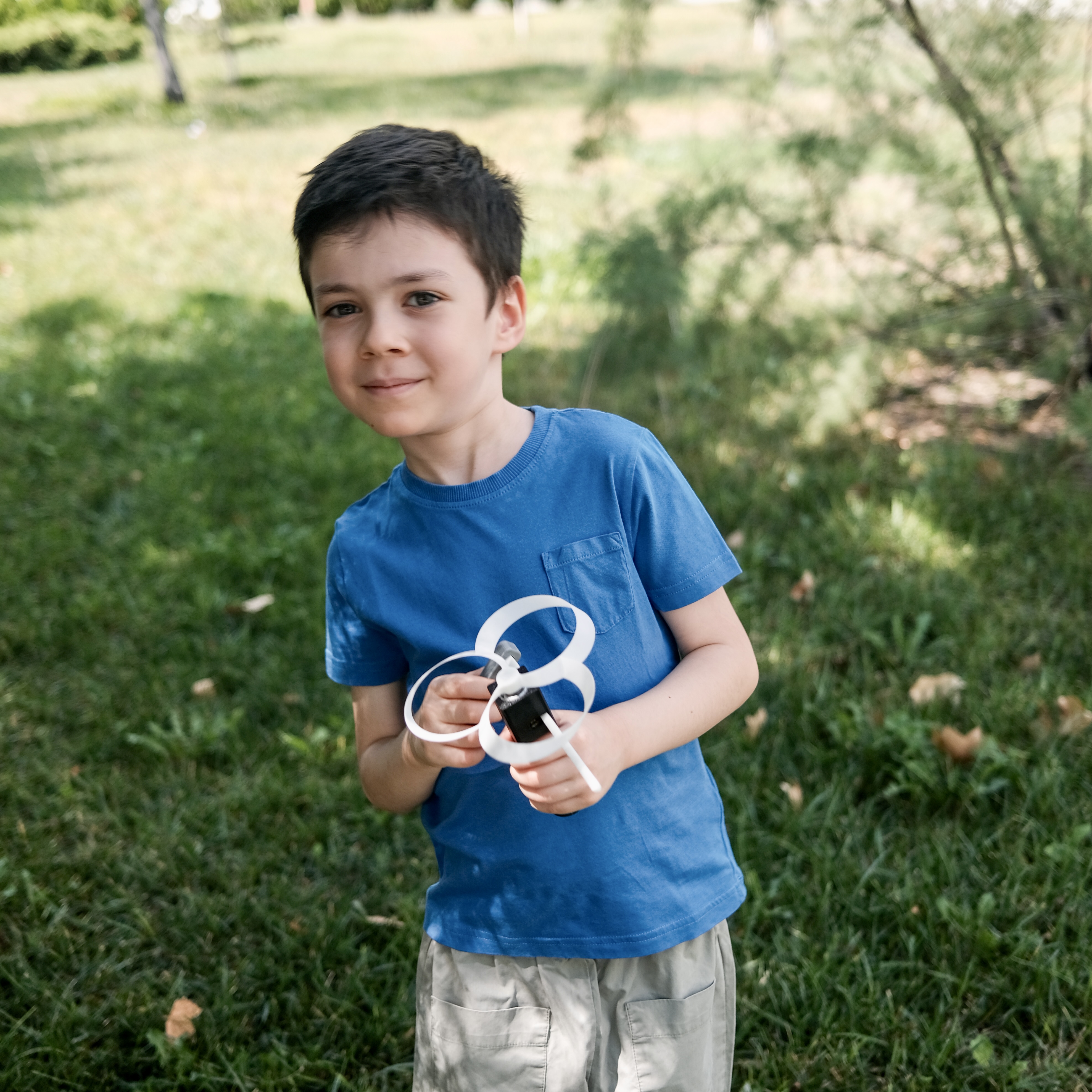
Bonus, happy pictures:
And a video:
I would like to hear your thoughts about this post. If you want to share with me, you can find me on Twitter.